Connectors Guide
Roversa has four connectors located on the rear of the device. There are two I2C connectors and two GVS connectors, one digital and one analog. This allows you to add various sensors, motors, and extensions to customize and add to Roversa.
On this page: GVS Digital · GVS Analog · I2C
GVS Digital
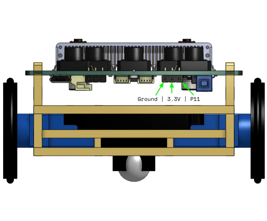
The GVS (ground, voltage, signal) Digital pins allow you to connect a standard .1”/2.54mm header or Dupont style connector to Roversa. These pins provide a ground and 3.3V signal as well as an input/output digital pin from the micro:bit, P11. This pin is also attached to Button B on the micro:bit.
GVS Analog
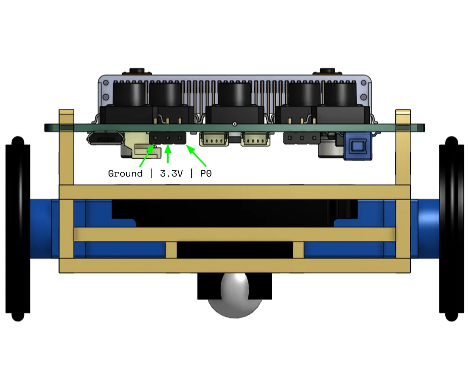
The GVS (ground, voltage, signal) Analog pins allow you to connect a standard .1”/2.54mm header or Dupont style connector to Roversa. These pins provide a ground and 3.3V signal as well as an input/output analog or digital pin from the micro:bit, P0. Analog pins on the micro:bit can read and write values from 0-1023. This pin is also attached to the speaker on the V2 micro:bit and can be used as one of the touch pins.
I2C
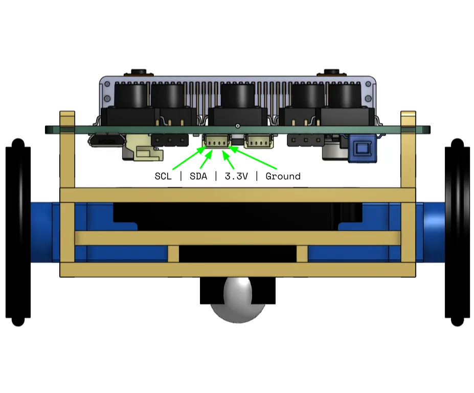
The two I2C JST-SH 1.0mm connectors allow you to connect various I2C sensors directly to the I2C pins on Roversa. These connectors are the same as the Stemma QT and Qwiic connectors. The I2C pins are pins P19 - SCL (Clock) and P20 - SDA (Data) on the micro:bit. There are 2 connectors on the board allowing you to add all kinds of sensors and reduce the amount of sensors you might need to daisy-chain together. Both of these connectors are exactly the same. There are two 4.7kΩ pull-up resistors on the SDA and SCL lines and are also shared with the on-board accelerometer, gyroscope, and magnetometer. Many small sensor breakout boards already contain pull-up resistors if needed.